Balance Bot
Position control of an inverted pendulum robot
Code: IMU_Encoder
Overview
Balance bot is a self-balancing Arduino robot, featuring a PID controller for angle and position tracking. A Madgwick complementary filter utilizes a fourth order Runge Kutta scheme (RK4) to estimate orientation as a quaternion. Additionally, wheel encoders are employed to provide accurate position estimation.
Hardware
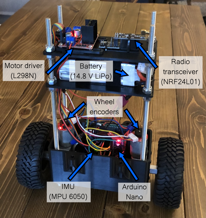
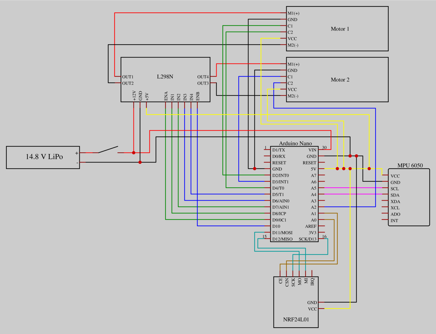
This robot uses an Arduino Nano, worm gear motors with magnetic wheel encoders, an inertial measurement unit (IMU), and a motor driver. Additionally, a radio transceiver has been integrated into the build for potential future expansion. Balance bot was designed in OnShape, with the battery placed towards the top to increase the moment of inertia, thereby enhancing the stability of the robot.


Orientation Estimate
Using the IMU dynamic model from [1] with a RK4 integration scheme, IMU measurements are used to propagate the IMU pose over time. However, since heading and direction of gravity are in general not directly observable using accelerometer and gyroscope measurements, there will be drift on all axes of rotation (and unknown initial orientation).
To address roll/pitch drift, the complementary filter presented in section 7.2 of [2] is employed to heuristically estimate the direction of gravity. Yaw drift cannot be accounted for without an additional sensor such as a magnetometer.
An IMU calibration procedure was written (imu calibration script) to account for axis sensitivity, axis misalignment and bias. Processing was used along with Arduino script imu_example.ino to visualize the IMU orientation as shown in Video 1.
Position Estimate
The magnetic wheel encoders can be used to measure angular displacement of the motor shaft. In combination with the wheel radius and gear ratio, this measurement allows us to estimate the position of the robot. A PID controller is employed so position control can be achieved as shown in Video 2, in which the robot resets to the original position after being moved. The code to control the robot can be found here: balance_bot.ino
Future Directions
- Use an EKF to fuse IMU and encoder measurements to get high quality position and heading estimates.
- Implement a remote controller using the radio transceiver.
References
[1] K. Sun, K. Mohta et al., “Robust Stereo Visual Inertial Odometry for Fast Autonomous Flight,” 2018 arXiv
[2] S. Madgwick, “AHRS algorithms and calibration solutions to facilitate new applications using low-cost MEMS,” 2014 Thesis (Ph.D.)